I have a Danby DKC14SLDB 5.2 cubic Foot Single Draught Kegerator I purchased several years ago. Several times a year I find myself with two pony kegs of homebrew I want on tap. Only having a single draught faucet was really cramping my style. I decided instead of purchasing a whole new tower with two faucets ($90) or an adapter ($70), which would have required the additional faucet anyhow, I would make it work on the cheap. I set out by purchasing the following items form Beveragefactory.com (note I have been home brewing for a long time and as such I have some old Coca-Cola pin-lock kegs that I normally use – please purchase whatever keg coupling is appropriate for your application):
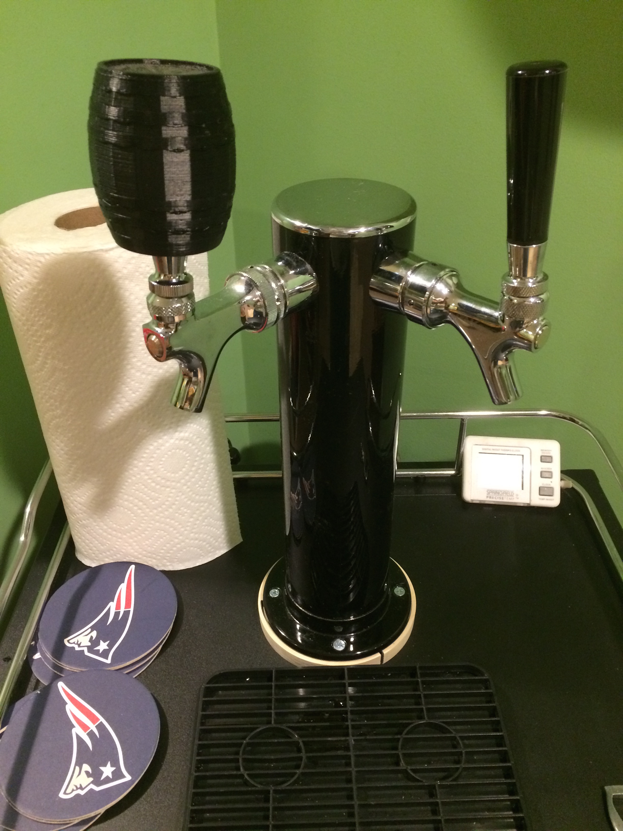
When the items arrived I marked out a location that would put the new faucet 90 degrees from the original at the same height and installed it in the tower. This was done by masking the area with masking tape and using a combination square to mark a center hole location. A center punch was used to start the drill and a 1/8″ hole was drilled with a standard drill bit. After the starting hole was drilled I used a large step-bit to enlarge the hole in the steel column to the appropriate size (7/8″). I used the larger of the two so I didn’t have to remove the existing faucet in the column. The faucet was installed, tubing attached and fed into the kegerator. The faucet worked great however it was 90 degrees perpendicular to the original and pointed off to the side. It would be ideal if both faucets were facing front.
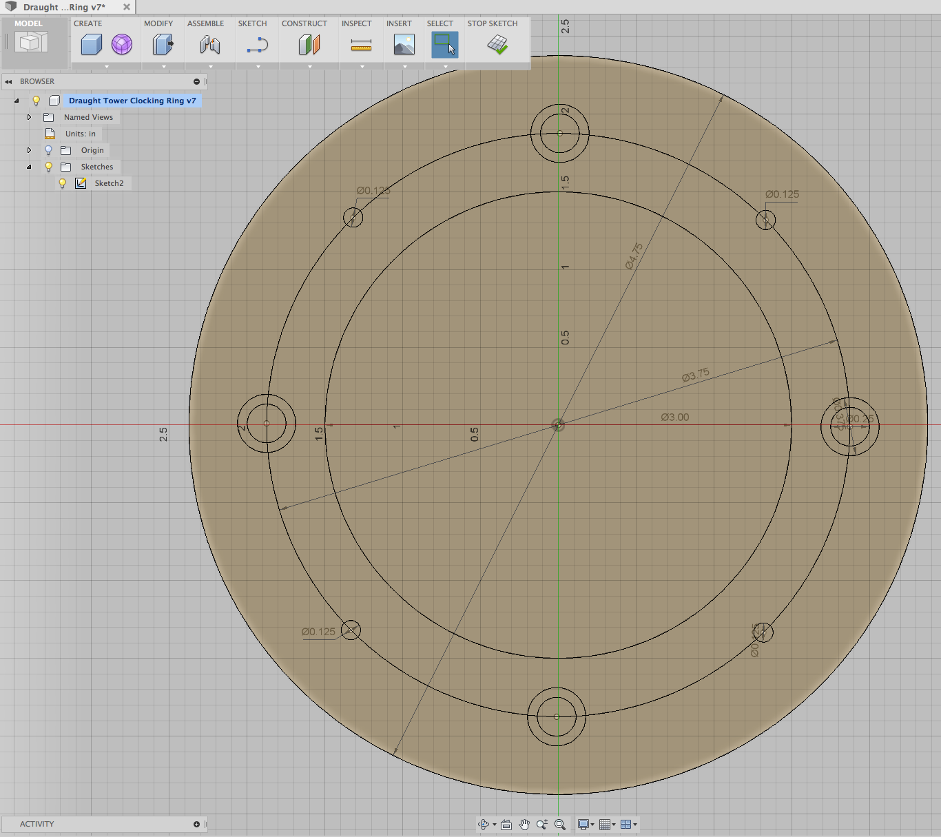
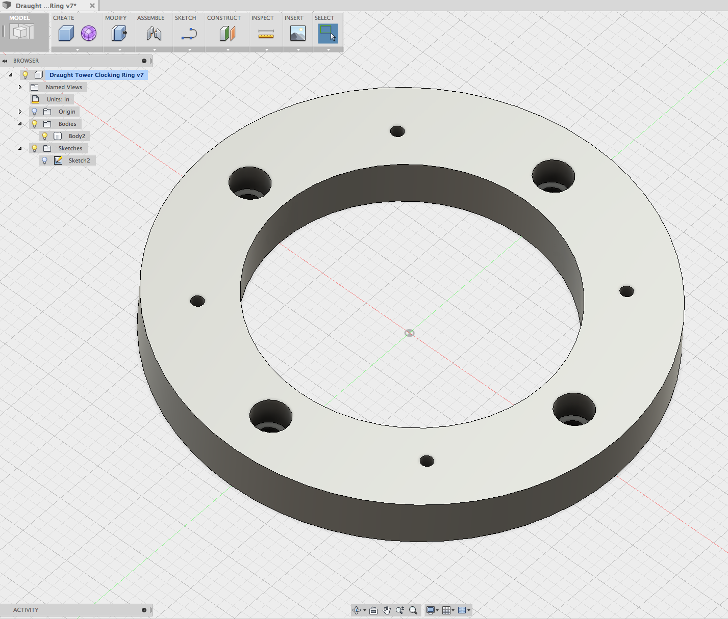
CAD Design:
To remedy this problem I fired up Autodesk Fusion 360 and created a quick clocking ring to rotate the tower 45 degrees. I took some quick measurements of the tower base and transcribed them into a sketch in Fusion 360. This took about 10 minutes from start to 3D model. It was a little too large to print on my old Thing-O-Matic and I wasn’t sure how plastic would hold up in this application so I opted for wood. Please note you can find the STL file below if you want to try to 3D print this part.
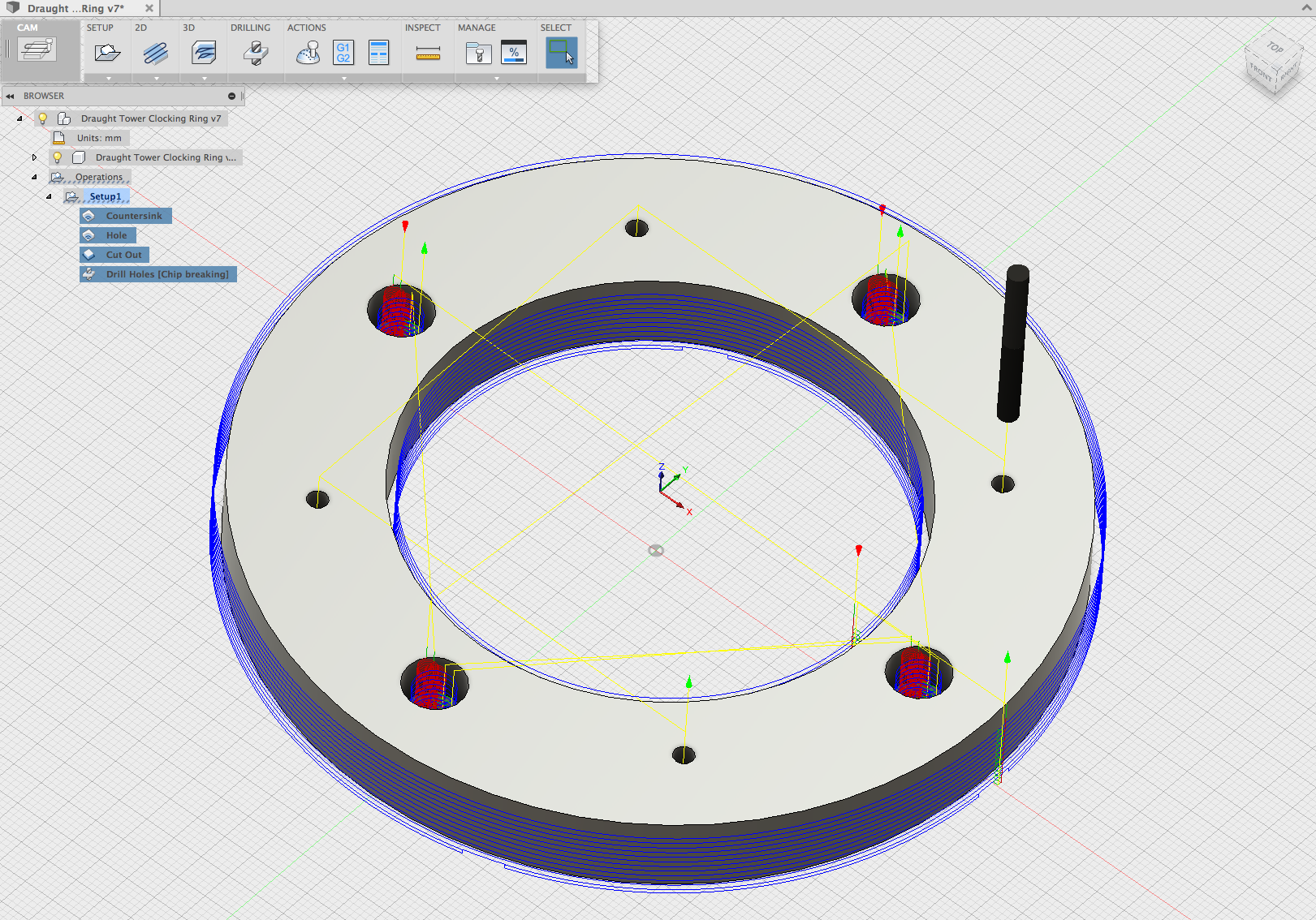
CAM Setup:
I entered the Fusion 360 CAM suite and setup some milling operations for my ShapeOKO 2. Fusion 360’s cam operations are intuitive and very fast running on the machine. All the operations to cut out this 3D part were “2-D”. There are 3 milling operations and one drilling operation setup here. All operations use the same tool, a 1/8″ two flute center cutting endemill. First the “Countersink” operation uses the high-speed milling operations to pocket out the 3/8″ area where the existing machine screws heads go. The second operation “hole” makes 1/4″ through holes for the machine screws. Both the first and second operations use the 2-D Pocket operations to quickly remove material. The third operation “Cut out” uses the 2D contour operation to cut out the ring leaving holding tabs. The final operation “Drill Holes” pecks into the material to drill 1/8 pilot holes to accept wood screws in the towers newly rotated position.
Cutting and Finishing:
I exported the g-code from Fusion 360 using the post-processor I modified for it. You can find that here. The job took about 10 minutes to cut on my ShapeOKO 2 with DW660 trimmer. Code was sent using Universal G-Code Sender but in the future I think I will try out Chillipepr. I could have likely sped up the federates a little more but I wasn’t sure if I was going to cut this out of hard wood or something softer. It so happened that I had no 1/2″ thick hardwood laying around my shop so I opted for some Poplar. When the cut was finished I sanded off the exterior tabs on my disk sander followed by a quick surface sanding with 220 grit sandpaper to take off any fuzziness.
I took it to my bandsaw and cut it in half for easier installation. This part is optional – but I had two beers on tap and didn’t want to be hassled with removing the keg couplers from the beer lines so I could snake them through the center opening. My bandsaw has about a 1/8″ kerf so some rubber strips about that thickness were cut to fill those gaps before the machine screws were tightened down. The clocking ring was mounted using the existing machine screws and 4 new #8 x 3/4″ wood screws. Now all I need is a larger drip tray.
Design Files:
draught_tower_clocking_ring.stl – STL File if you want to 3D Print
draught_tower_clocking_ring.f3d – Fusion 360 Design Archive
keg tap handle – The 3D printed barrel tap handle shown in the picture