
Fusion 360 is an awesome CAD/CAM package from Autodesk. The licensing is reasonable, the support is good, the CAD/CAM is top notch and it runs on both macOS and Windows 10. Recently I acquired a Banggood A3 2.5W Laser Engraver and decided, since I had a good tool chain for cutting on my ShapeOKO I may as well carry that over to my Laser. I started with GRBL 1.1d (edge) release which was just just came out and built it using the PlatformIO IDE. I did this on my Mac and uploaded the resultant hex file using Xloader on my PC that’s connected to the laser. The compiled hex I used for my Atmega328 Nano that was installed on my laser is below. Please note if you were not running GRBL 0.9 on your laser prior you should remove the nano and set the jumper to 0.9 on the controller board. Note if you are using a Smoothie board you can just follow along with the tool path and gcode generation portion that follows and use the Smoothie post that is already included. The GRBL post that’s included does not support the new waterjet/laser features.
grbl_1-1d_edge-hex (Arduino Nano w/ ATmega 328p GRBL 1.1d Firmware 32KB) (depreciated – please use 1.1e)
nano_grbl-edge-1.1e.hex (Arduino Nano w/ ATmega 328p GRBL 1.1e Firmware 32KB) (Updated 02/27/2017)
I recommend downloading the source code and building yourself. I have however included my compiled hex here for future reference. I utilized XLoader to load the firmware onto my laser from the Windows 10 Laptop normally used to drive the laser. After the firmware was installed the configuration for the machine needs to be written. This includes if you were previously running GRBL 0.9 since the EEPROM map is slightly different. I utilized the latest nightly build of Universal Code Sender (USG Platform) which is compatible with the new reporting from GRBL 1.1d.
The configuration I use for my Banggood A3 2.5W Engraver is as follows. There is also a zip file below that contains this same information. The values in red are what was changed from the firmware defaults. The new values can be uploaded line-by-line or by sending the file attached below to the Laser.
$0=10 (microseconds, Step pulse time: Sets time length per step. Minimum 3usec.)
$1=255 (milliseconds, Step idle delay: Sets a short hold delay when stopping to let dynamics settle before disabling steppers. Value 255 keeps motors enabled with no delay.)
$2=0 (mask, Step pulse invert: Inverts the step signal. Set axis bit to invert (00000ZYX).)
$3=0 (mask, Step direction invert: Inverts the direction signal. Set axis bit to invert (00000ZYX).)
$4=0 (boolean, Invert step enable pin: Inverts the stepper driver enable pin signal.)
$5=0 (boolean, Invert limit pins: Inverts the all of the limit input pins.)
$6=0 (boolean, Invert probe pin: Inverts the probe input pin signal.)
$10=3 (mask, Status report options: Alters data included in status reports.)
$11=0.010 (millimeters, Junction deviation: Sets how fast Grbl travels through consecutive motions. Lower value slows it down.)
$12=0.002 (millimeters, Arc tolerance: Sets the G2 and G3 arc tracing accuracy based on radial error. Beware: A very small value may effect performance.)
$13=0 (boolean, Report in inches: Enables inch units when returning any position and rate value that is not a settings value.)
$20=0 (boolean, Soft limits enable: Enables soft limits checks within machine travel and sets alarm when exceeded. Requires homing.)
$21=0 (boolean, Hard limits enable: Enables hard limits. Immediately halts motion and throws an alarm when switch is triggered.)
$22=0 (boolean, Homing cycle enable: Enables homing cycle. Requires limit switches on all axes.)
$23=0 (mask, Homing direction invert: Homing searches for a switch in the positive direction. Set axis bit (00000ZYX) to search in negative direction.)
$24=25.000 (mm/min, Homing locate feed rate: Feed rate to slowly engage limit switch to determine its location accurately.)
$25=500.000 (mm/min, Homing search seek rate: Seek rate to quickly find the limit switch before the slower locating phase.)
$26=250 (milliseconds, Homing switch debounce delay: Sets a short delay between phases of homing cycle to let a switch debounce.)
$27=1.000 (millimeters, Homing switch pull-off distance: Retract distance after triggering switch to disengage it. Homing will fail if switch isn't cleared.)
$30=1000 (RPM, Maximum spindle speed: Maximum spindle speed. Sets PWM to 100% duty cycle.)
$31=0 (RPM, Minimum spindle speed: Minimum spindle speed. Sets PWM to 0.4% or lowest duty cycle.)
$32=1 (boolean, Laser-mode enable: Enables laser mode. Consecutive G1/2/3 commands will not halt when spindle speed is changed.)
$100=80.000 (step/mm, X-axis travel resolution: X-axis travel resolution in steps per millimeter.)
$101=80.000 (step/mm, Y-axis travel resolution: Y-axis travel resolution in steps per millimeter.)
$102=80.000 (step/mm, Z-axis travel resolution: Z-axis travel resolution in steps per millimeter.)
$110=5000.000 (mm/min, X-axis maximum rate: X-axis maximum rate. Used as G0 rapid rate.)
$111=5000.000 (mm/min, Y-axis maximum rate: Y-axis maximum rate. Used as G0 rapid rate.)
$112=5000.000 (mm/min, Z-axis maximum rate: Z-axis maximum rate. Used as G0 rapid rate.)
$120=600.000 (mm/sec^2, X-axis acceleration: X-axis acceleration. Used for motion planning to not exceed motor torque and lose steps.)
$121=600.000 (mm/sec^2, Y-axis acceleration: Y-axis acceleration. Used for motion planning to not exceed motor torque and lose steps.)
$122=10.000 (mm/sec^2, Z-axis acceleration: Z-axis acceleration. Used for motion planning to not exceed motor torque and lose steps.)
$130=370.000 (millimeters, X-axis maximum travel: Maximum X-axis travel distance from homing switch. Determines valid machine space for soft-limits and homing search distances.)
$131=300.000 (millimeters, Y-axis maximum travel: Maximum Y-axis travel distance from homing switch. Determines valid machine space for soft-limits and homing search distances.)
$132=200.000 (millimeters, Z-axis maximum travel: Maximum Z-axis travel distance from homing switch. Determines valid machine space for soft-limits and homing search distances.)
banggood_a3_grbl-config (GRBL 1.1d/e Banggood A3 Configuration file 1.5 KB)
After the firmware is uploaded make sure you can jog the machine around. You may want to also setup a couple macros in Universal G-Code Sender. Creating a “Laser Off” (M3 S0; M5;) and “Weak Laser” (M3 S5) macro is almost mandatory. Note these are based on my laser performance and the 0-1000 RPM spindle range in my configuration. If you have a more powerful laser or different RPM range you may want to revisit this “S” value. After the firmware is updated It’s time to do some CAD/CAM in Fusion 360.
I started by making a customized CAM post processor for my Banggood A3 2.5W Laser Engraver. I started with a suitable one that supported Laser already, namely the smoothie post processor. I found and modified a provided original postprocessor as follows:
- Click on the link to the application and follow it to the original location by right-clicking and selecting “Show Original”.
- Follow Libraries/Applications/CAM360/DATA/Posts in Finder. Method and location will likely differ on Windows.
- Copied smoothie.cps to my desktop and renamed it Banggood_A3.cps.
- Made my modifications and then stored it in my local posts folder. On the mac this is located at ~/Autodesk/Fusion 360/CAM/Posts.
- You may want to store the post “in the cloud” – this will let you use it no matter what machine you are doing your CAM work on. These go in the CAMPosts directory in your A360 Drive.
banggood_a3 (Fusion 360 CAM Post for Banggood A3 Laser 6KB)
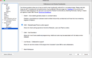
You will need to enable the “Preview” Waterjet/Laser/Plasma CAM features for this to work. Go to your preferences and select “Preview” and enable the feature as shown below.
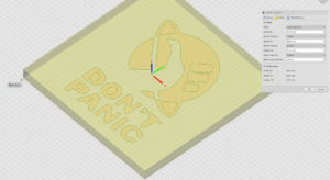
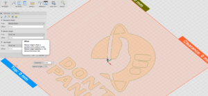
I imported a DXF and inserted it into a new design and extruded it. Extruding it is an optional step since this is a 2D operation anyhow. I selected CAM and created a new setup. In my case I like to start at the center of my work. This is pure preference but I find it’s much easier for me to setup my CNC Router with the bit at the center of the material on the top surface. With other lasers such as a K40 you may need to have your minimum coordinate be 0,0 in the lower left. This however is highly dependent on how the machine is configured and if there are “soft” stops configured. Set the operation type as Waterjet/Laser/Plasma and the appropriate work coordinate system. The setup of the stock isn’t really important – just make sure it’s width and length are large enough to cover your model or match the material you will be cutting. In my case I have a 3.5″ x 3.5″ x 0.25″ piece of material with the WCS (0,0) at the centerpoint.
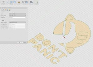
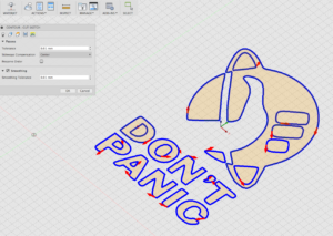
After the setup it’s on to generate the tool paths. Select the “Waterjet” icon and in the setup change it to Laser Cutting (Through Auto). Adjust your feed rates appropriately dependent on materials and laser power.
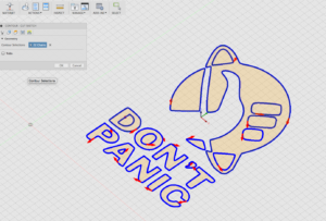
Next select the contours that you want to cut. Make sure your sketch (or bodies) are visible for this. If you want it cut in a certain order select it in the order you want it cut.
For stock offsets I set everything to zero. I have no “Z” axis on my machine and don’t need Z moves out in the GCODE.
For passes I set the sideways compensation to center. Setting it left or right causes the post to fail since I does not support tool compensation. In addition I want to cut on the line not beside it. I keep smoothing turned on.
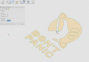
In the linking tab this will greatly affect the output GCODE. If you don’t change these settings for lead-in entry and lead-out entry to unchecked it will do helical moves to try to maintain speed when jumping between locations. While the GRBL controller supports this some senders don’t render these moves properly. Also we are not moving too much mass so we don’t really need to get fancy when changing directions or jumping around. You can also specify an entry point where you want it to start lasering. This is optional it will generally start closest to 0,0 unless you told it to preserve order in the passes settings.
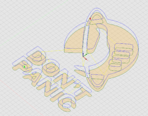
Once completed the tool path can be generated. It might be good to save this CAM setup as a template so if you have another design you can just apply the template without fiddling with all the settings! At this time you can simulate it. It’s probably not a bad idea to do so – just to make sure the the laser isn’t firing when it’s not desired to and you didn’t miss any cuts like the inside of the letter “A”.
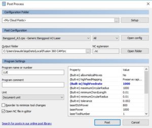
At this time the tool path can be “posted” and written out. Right-clock the tool path and select “Post Process”. Select the post processor either from your cloud posts or the local directory where you have stored it. I set the “highFeedrate” to 1000 – which it should default to if working in mm. The only other thing you might want to adjust here is the “laserPower”. I have it default to 1000 which matches the default GRBL configuration for max RPM. With this setting the laser will be firing at 100%. When you press OK the post processor will run and write out a G-Code file. (Windows post process pane shown – Mac version differs)
Now all that’s left to do is to send it to the Laser. For this I use Universal Code Sender – the latest nightly build which supports version 1.1 status reporting.
- Open the file
- Position your work
- Make sure the Zero is set to the same location you specified for your work coordinate system
- Send the file
- Enjoy the results
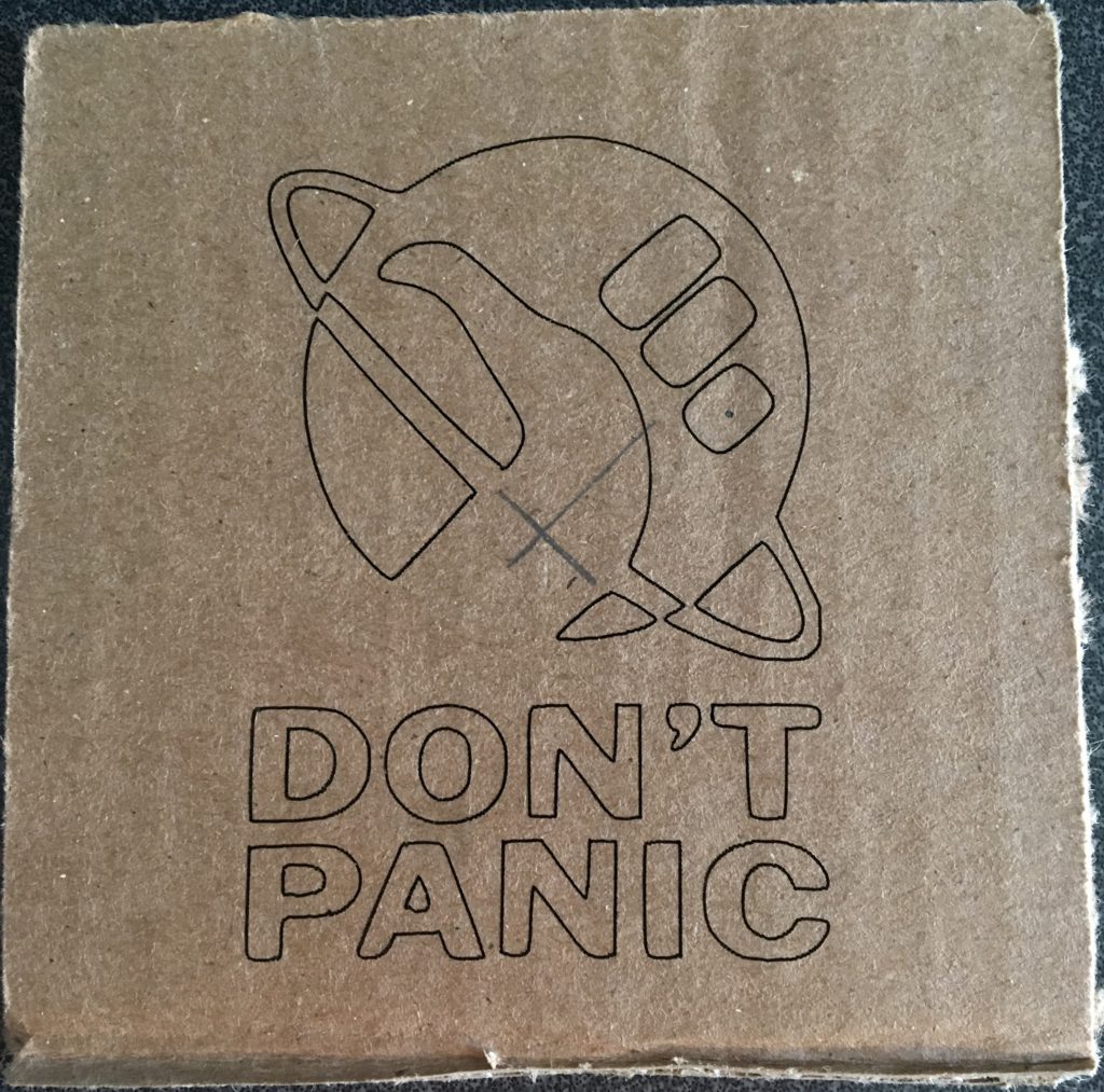
Keep following my blog as I will be updating it with additional information regarding this equipment.